Hardware documentation
Automator – electrical and control system
This document describes the complete electrical and electromechanical hardware of the Automator system.
It is derived from the system schematic, explicit author clarification, and the authoritative printer.cfg.
Software behaviour, motion planning logic, and mechanical CAD are intentionally excluded.
1. System overview
The Automator hardware consists of:
- Raspberry Pi (host controller, cameras, web UI)
- MKS Robin Nano V3.1 (Klipper motion controller)
- Independent AC-powered DC supplies
- Stepper-driven X, Y, and Z motion
- Plate handling system:
- Vacuum pump
- Air solenoid valve
- Suction cup
- Servo-driven suction cup rotation
- Imaging system:
- LED illumination
- USB camera (QR scanning)
- Raspberry Pi camera (plate imaging)
- Safety systems:
- AC-side emergency stop
- Door interlock
- Axis end-stops
All safety-critical power removal is implemented in hardware.
2. Power architecture
2.1 AC input and emergency stop
- Mains AC feeds all DC power supplies
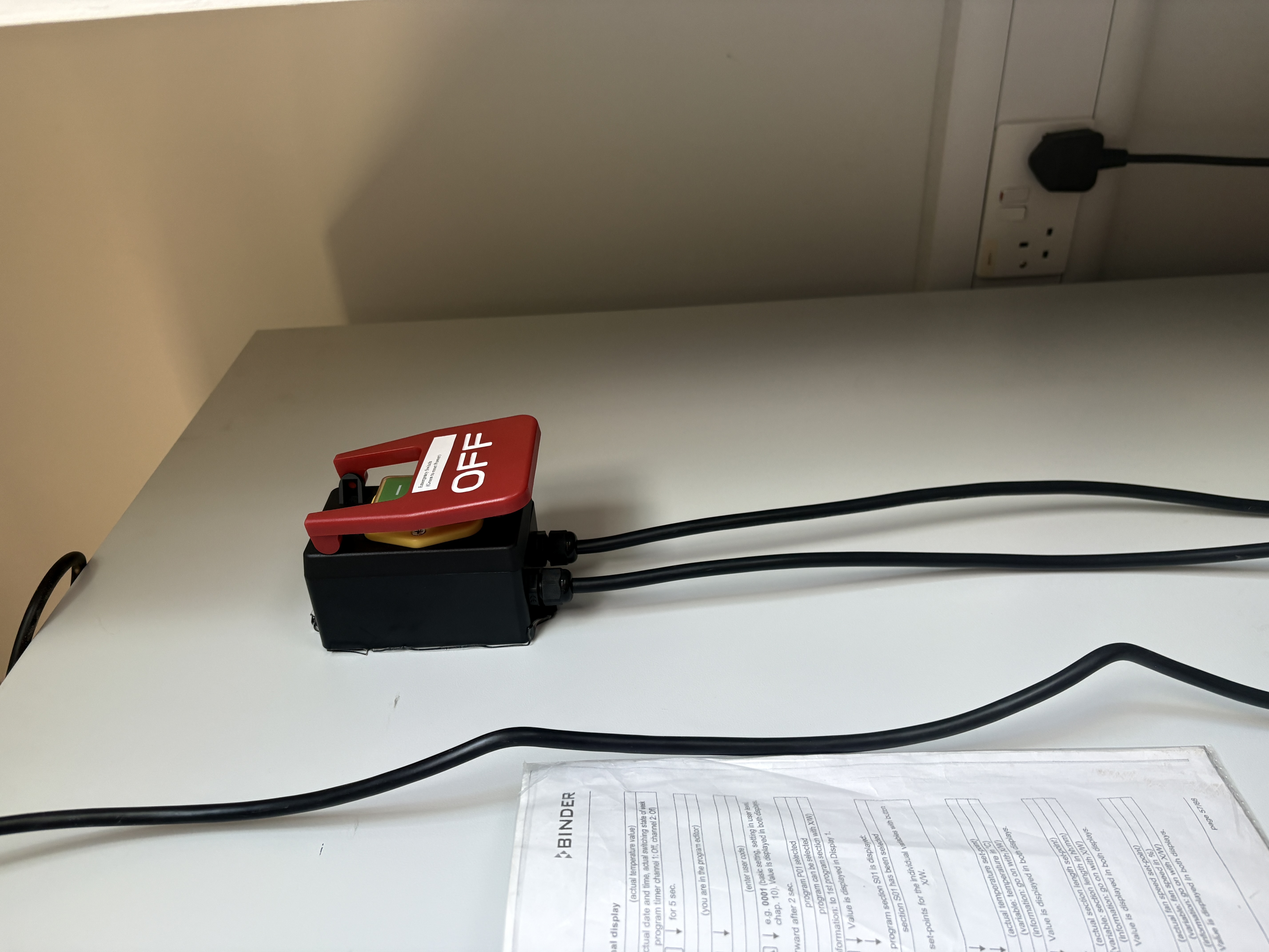
- A physical, latching emergency stop switch is wired on the AC side
- Activating the E-stop removes AC power from:
- 12 V DC power supply
- 5 V peripheral DC power supply
- Raspberry Pi 5 V adaptor
This is a true electrical power cut and does not rely on software.
Reference photo of the external E-stop wiring: images/estop.jpg.
2.2 DC power domains
| Rail | Source | Loads |
|---|---|---|
| 12 V DC | AC to DC adaptor | MKS Robin Nano V3.1, X/Y/Z stepper motors, vacuum pump, air solenoid |
| 5 V DC (peripherals) | Buck converter | Servo, relay coils, sensors, LED logic |
| 5 V DC (Raspberry Pi) | Separate AC to DC adaptor | Raspberry Pi only |
| GND | Common | All DC domains |
Explicit clarifications:
- The buck converter does not power the Raspberry Pi
- The Raspberry Pi uses a dedicated isolated 5 V supply
- 12 V is used only for motors, the MKS board, and vacuum hardware
- Both 12 V and 5 V supplies are disconnected by the AC emergency stop
3. Power tree
Mains AC
└── Emergency Stop (AC-side, latching)
    |
    |
    ├── AC --> 12 V DC PSU
    │          ├── MKS Robin Nano V3.1
    │          │   ├── X stepper motor
    │          │   ├── Y stepper motor
    │          │   └── Z stepper motor
    │          |
    │          └── 12 V --> 5 V Buck Converter
    │                       ├── Servo motor
    │                       ├── Proximity Sensor
    |                       ├── Vacuum Pump
    |                       ├── 80 MM 5V fans(2 no.s)
    |                       ├── Small 5v Fan Z motor
    |                       ├── Air Solenoid
    │                       ├── Relay Module
    │                           └── LED Strip light
    │
    └── AC --> 5 V DC PSU (Raspberry Pi adaptor)
               └── Raspberry Pi
- All grounds are made common.
4. Controllers
4.1 Raspberry Pi
Functions:
- Klipper host
- Camera control
- Web UI and scheduler
Power:
- Dedicated 5 V adaptor
- Power removed by AC emergency stop
The Raspberry Pi does not directly drive motors, solenoids, or other inductive loads.
4.2 MKS Robin Nano V3.1
Functions:
- Motion control (Klipper MCU)
- Step / Direction / Enable outputs
- End-stop processing
- Servo and relay control outputs
Power:
- 12 V DC
- Disabled immediately by AC emergency stop
5. Motion system
| Axis | Motor Type | Supply |
|---|---|---|
| X | Stepper motor | 12 V |
| Y | Stepper motor | 12 V |
| Z | Stepper motor | 12 V |
Stepper power is fully removed when the emergency stop is activated.
6. Plate handling and imaging hardware
6.1 Vacuum system
Functional chain:
- Vacuum pump generates negative pressure
- Air solenoid valve controls vacuum routing
- Vacuum is applied to a suction cup
- Suction cup grips and lifts the Petri dish lid
Electrical control:
- Vacuum pump powered from 5 V via Air solenoid
- Air solenoid powered from 5 V
- Relay coils powered from 5 V peripheral rail
Vacuum is enabled only during imaging and is disabled by the emergency stop.
6.2 Servo – suction cup rotation
Purpose:
- Rotates the suction cup by 0 or 90 degrees
- Moves the lid away from the base plate during imaging
- Prevents obstruction of the raspberry camera field of view
Electrical details:
- Supply: 5 V (buck converter)
- Control: Software PWM
- Positions: 90° (over plate), 0° (rotated away)
6.3 LED illumination
- LED strip powered from 5 V peripheral rail
- Switched via relay
- Enabled only during image capture
7. Sensors and inputs
7.1 Door interlock
| Property | Value |
|---|---|
| Type | Proximity sensor |
| Logic | Normally open |
| Wiring | GPIO to GND |
| Pull-up | Enabled |
Opening the enclosure door triggers a controlled halt and park.
7.2 End-Stops
| Axis | End-stop |
|---|---|
| X | Present |
| Y | Present |
| Z | Present |
All end-stops are normally open and ground-triggered.
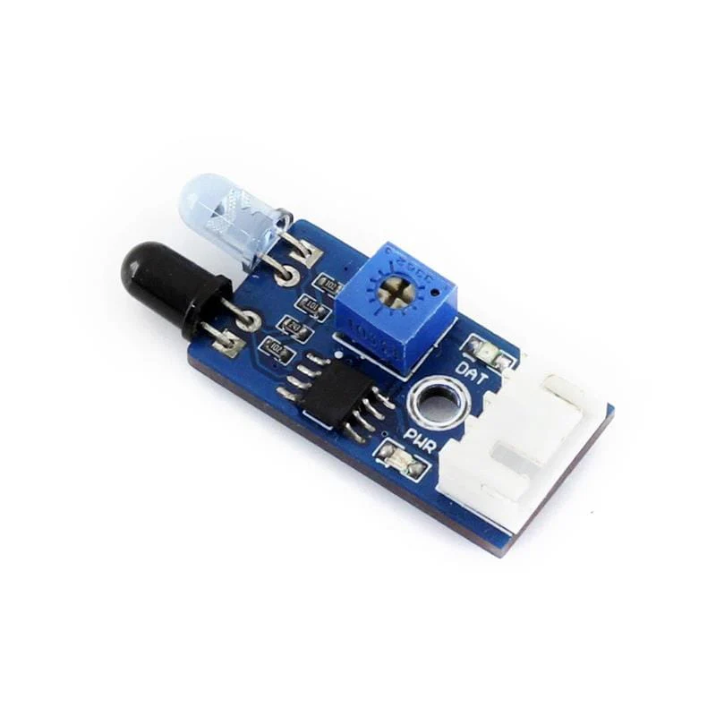
7.3 Proximity sensor
- Powered from 5 V peripheral rail
- Digital output
- Used to detect door open/closed state for the door interlock
8. Pin Mapping (from printer.cfg)
Controller MCU: STM32F407 (MKS Robin Nano V3.1)
8.1 Stepper motors and End-Stops
| Axis | Function | MCU Pin | Notes |
|---|---|---|---|
| X | STEP | PE3 | |
| X | DIR | PE2 | Inverted |
| X | ENABLE | PE4 | Inverted |
| X | ENDSTOP | PA15 | Pull-up enabled |
| Y | STEP | PE0 | |
| Y | DIR | PB9 | |
| Y | ENABLE | PE1 | Inverted |
| Y | ENDSTOP | PD2 | Pull-up enabled |
| Z | STEP | PB5 | |
| Z | DIR | PB4 | Inverted |
| Z | ENABLE | PB8 | Inverted |
| Z | ENDSTOP | PC8 | Pull-up enabled |
8.2 Actuators
| Device | Function | MCU Pin | PWM Type | Notes |
|---|---|---|---|---|
| Servo | Suction cup rotation | PA0 | Software PWM | 0–90° |
| Vacuum pump | Vacuum generation | PE5 | Software PWM | Drives relay |
| Solenoid valve | Vacuum routing | PB0 | Software PWM | Drives relay |
8.3 Raspberry Pi interfaces
| Function | Interface | Notes |
|---|---|---|
| Klipper host | USB serial | /dev/serial/by-id/... |
| Pi camera | CSI | Plate imaging |
| USB camera | USB | QR scanning |
No Raspberry Pi GPIO pins are used for motion control.
8.4 Raspberry Pi connections
8.4.1 GPIO
| GPIO | Function |
|---|---|
| GPIO 4 | LED relay pulse output |
| GPIO 13 | Buzzer output (physical pin 33) |
| GPIO 17 | START button input |
| GPIO 23 | Relay control for 5 V LED strip |
| GPIO 26 | Door sensor input |
| GPIO 27 | STOP / pause button input |
8.4.2 Cameras
| Interface | Device |
|---|---|
| CSI | Raspberry Pi camera (plate imaging) |
| USB | USB camera (QR scanning) |
8.4.3 USB interfaces
| USB Connection | Purpose |
|---|---|
| USB --> MKS Robin Nano V3.1 | Klipper serial communication |
| USB --> Camera | Imaging input |
9. Detailed hardware references and datasheets
This section provides manufacturer-level documentation for all major electronic components used in the Automator system.
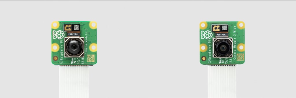
9.1 Raspberry Pi camera module 3
Function:
- High-resolution plate imaging
Interface:
- MIPI CSI-2 (22-pin ribbon cable)
Power:
- Supplied directly from Raspberry Pi CSI connector
Image:
References:
- https://www.raspberrypi.com/documentation/accessories/camera.html#camera-module-3
- https://www.raspberrypi.com/documentation/accessories/camera.html#hardware-specification
- https://github.com/raspberrypi/documentation/blob/master/documentation/asciidoc/accessories/camera/cm3.adoc
9.2 Raspberry Pi 4 model B
Role:
- Klipper host
- Camera acquisition
- Web UI and system orchestration
Processor:
- Broadcom BCM2711
Power:
- Dedicated 5 V AC adaptor
- Power removed by AC emergency stop
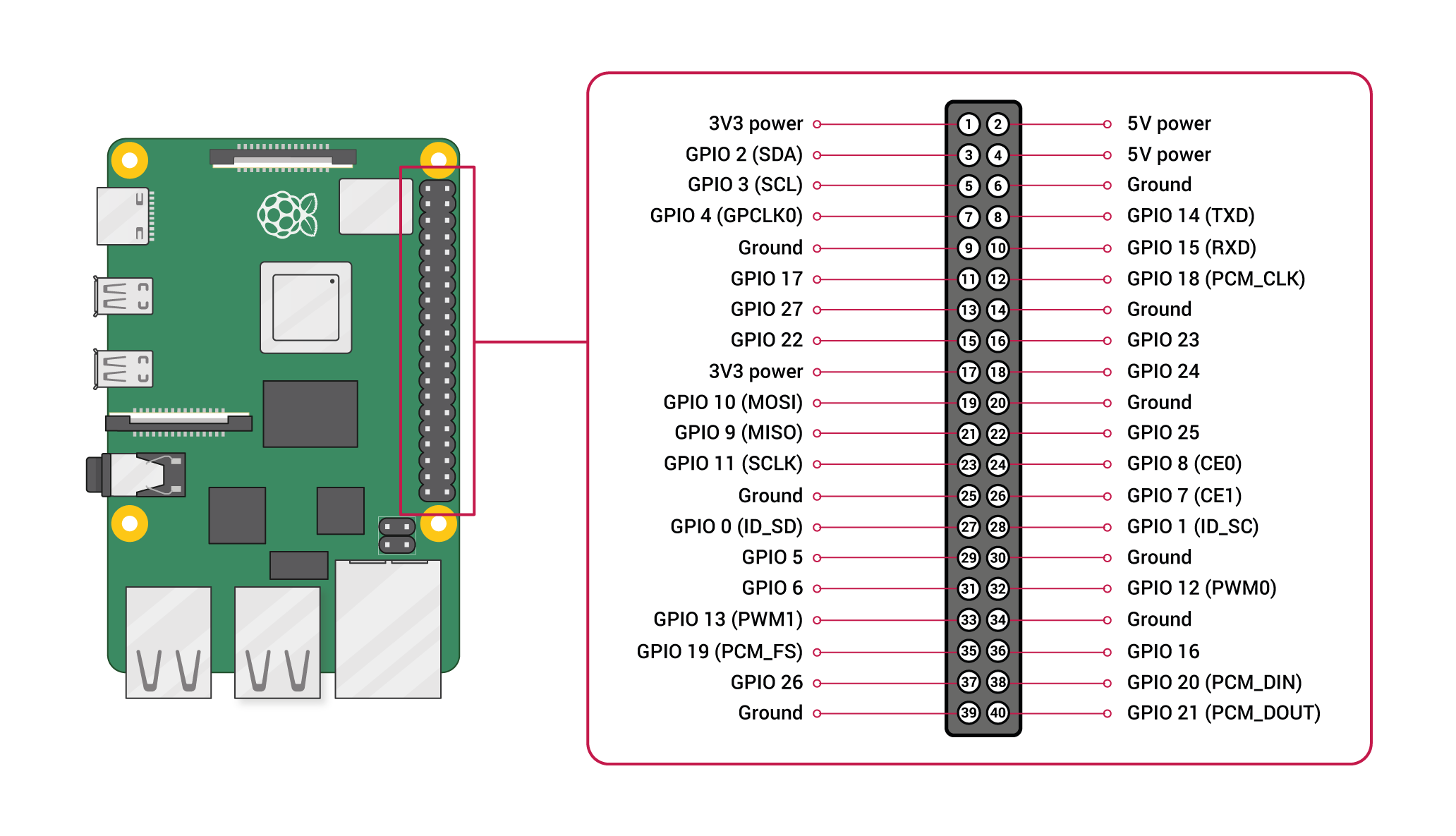
GPIO usage in Automator:
- GPIO 4 – LED relay pulse output
- GPIO 13 – Buzzer output (physical pin 33)
- GPIO 17 – START button input
- GPIO 23 – LED relay control
- GPIO 26 – Door sensor input
- GPIO 27 – STOP / pause button input
Image:
Datasheets:
Reference: https://www.raspberrypi.com/documentation/computers/processors.html#bcm2711
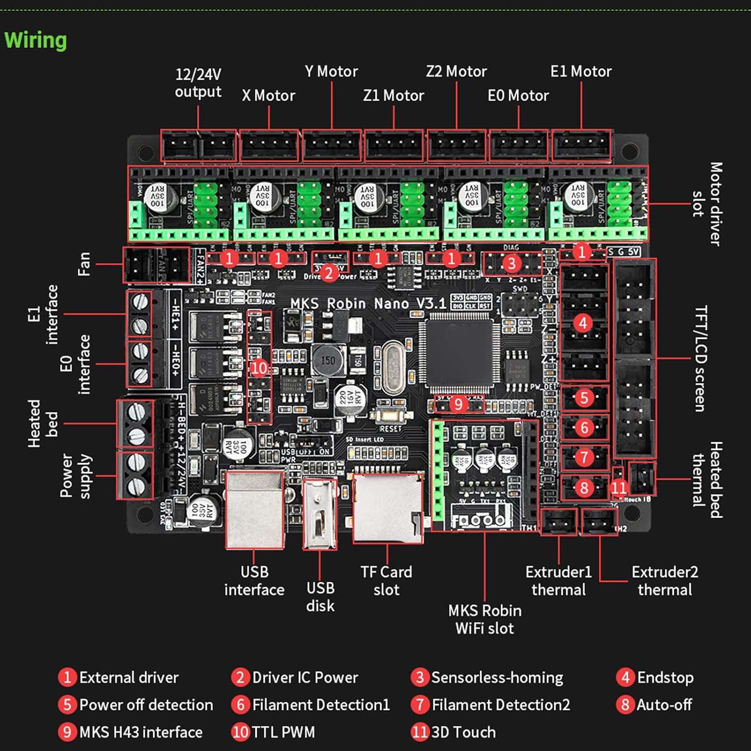
9.3 MKS Robin Nano V3.1 motion controller
Role:
- Motion control (Klipper MCU)
- Step/Direction outputs
- End-stop processing
- Servo and relay control
MCU:
- STM32F407
Power:
- 12 V DC
- Disabled by AC emergency stop
Image:
Hardware repository: https://github.com/makerbase-mks/MKS-Robin-Nano-V3.X/tree/main/hardware/MKS%20Robin%20Nano%20V3.1_001
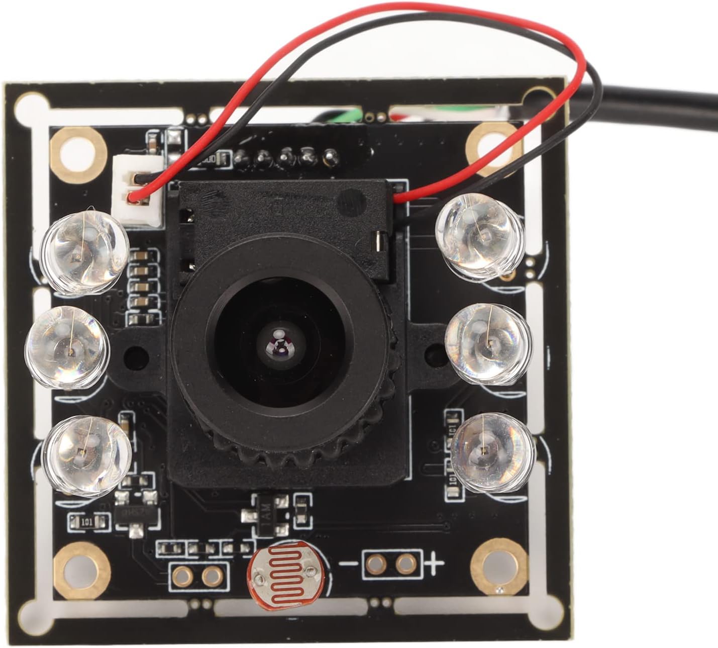
9.4 USB camera
Function:
- QR / code scanning
Interface:
- USB 2.0 (UVC compliant)
Power:
- 5 V supplied from Raspberry Pi USB port
Image:
Reference: https://www.amazon.co.uk/gp/product/B0BL77FXPV/
10. Parts list (electrical)
Controllers
- Raspberry Pi 4B 8 GB RAM, 64 GB Storage
- MKS Robin Nano V3.1
Power
- Latching emergency stop switch (AC rated)
Emergency stop switch:
- 12 V AC to DC power supply
- 5 V AC to DC power supply (Raspberry Pi)
- DC buck converter (12 V to 5 V, peripherals)
Motion
NEMA17:
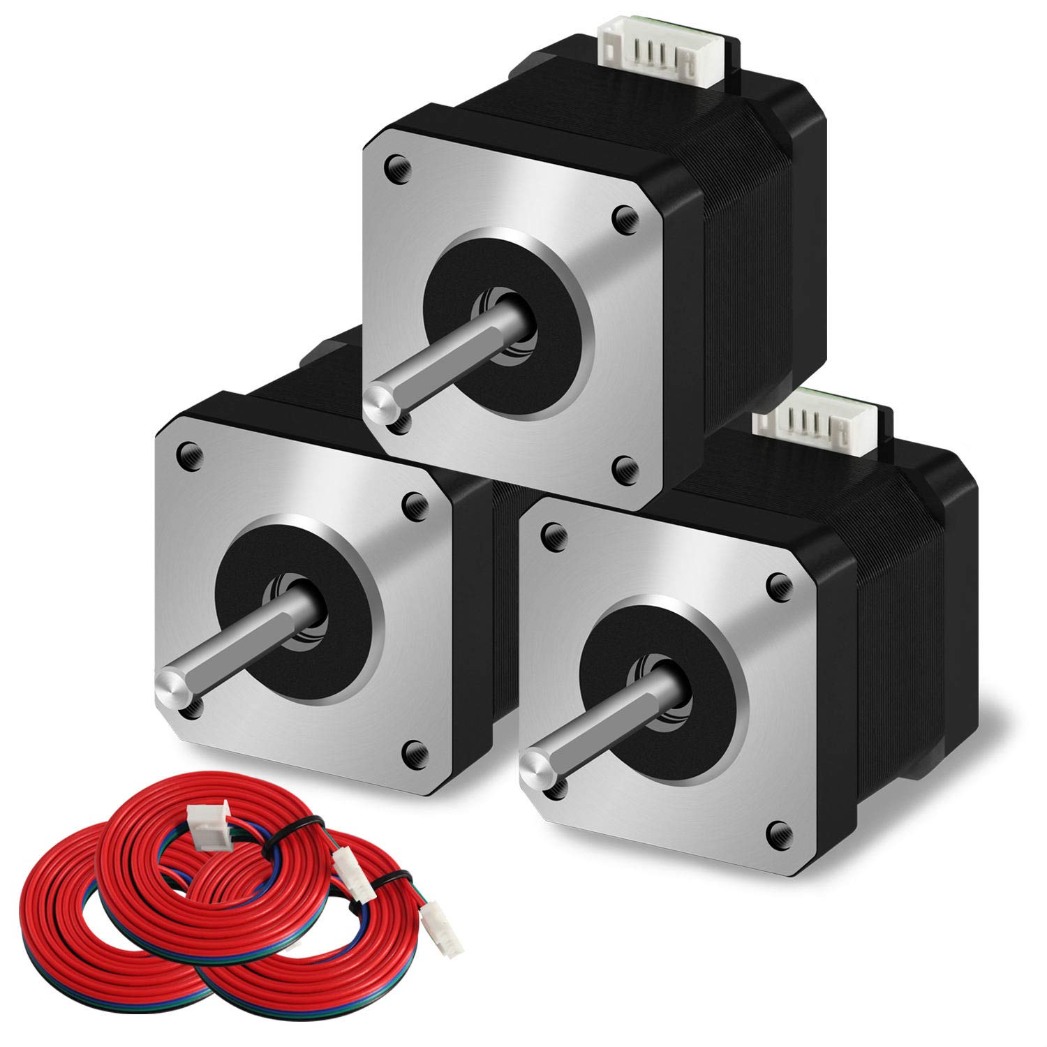
Plate handling
- Vacuum pump (12 V)
- Air solenoid valve (12 V)
- Suction cup and vacuum tubing
Vacuum Apparatus:

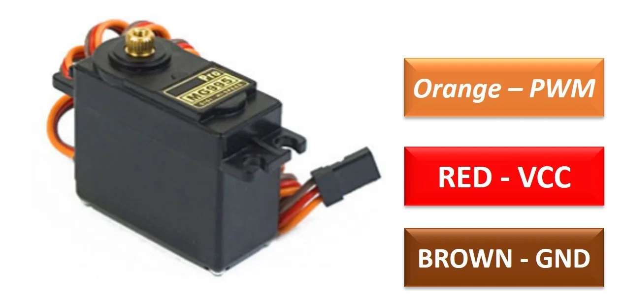
MG995 SERVO:
Switching and isolation
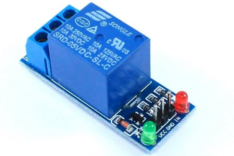
- Relay modules (5 V coil)
Relay:
Imaging
- LED strip or LED module
- Raspberry Pi camera
- USB camera
Sensors and safety
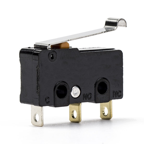
- Mechanical end-stop switches (X, Y, Z)
End stop switch:
- Proximity sensor
Proximity sensor:
Miscellaneous
- Wiring and connectors
- Fuses (via Emergency Stop)
- Grounding hardware
11. Safety notes
- Emergency stop removes power at the AC level
- Motors, solenoids, and logic do not rely on software for shutdown
- Software safety features are supplementary only
12. Related files
| Path | Description |
|---|---|
| hardware/ | Schematics and wiring |
| config/printer.cfg | MKS Pin configuration |
| documentation/ | Network configuration |
| mechanical/ | CAD and assemblies |
13. Disclaimer
This hardware design is provided as-is for research use. Users are responsible for electrical safety, compliance, and validation.
Refer to main project repository for disclaimer, License and use
Document updated 30/06/2026 Rohan R
The Sainsbury Laboratory, Norwich